With the front suspension done, all I needed was rear suspension and I’d have a roller. The original midgets of the late ’40s used a transverse leaf spring and either hairpins or split wishbones. The look of the hairpins is such a classic that I decided to try to replicate that look on my midget.
Click through for more hairpins!
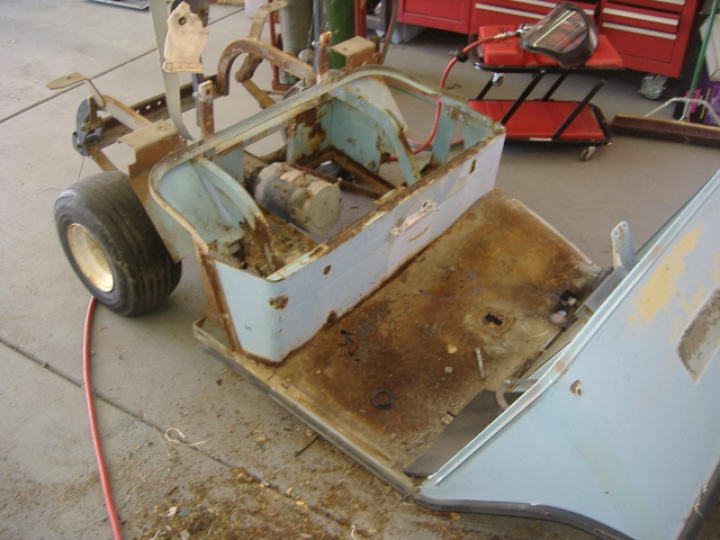
The rear suspension on the golf cart was a parallel leaf setup, much like millions of cars and trucks have had for the last 40 years. The difference in this case was that the 36 volt motor was bolted directly to the rear differential. No driveline, no transmission, no hassle. The motor just hung out under the golf cart seat.
Now, on the midget, there isn’t quite that much room under the seat. In fact, there is only about 5″ of space under the seat. No room for that rompin’, stompin’ E-Z-GO drive train. What to do? Disconnect the motor and add a driveshaft? No. The simple, elegant solution was to turn the whole arrangement around backwards. D.C. Electric motors don’t care whether they are running forward or backward, and will run the same speed both ways. Just reverse the polarity of the circuit and presto. The only downside of this arrangement is that the ring and pinion is being driven backward, on the passive side of the ring gear. In the long-term, this is probably bad for the gears, but this vehicle is light enough, weak enough, and gets used seldom enough that I am not too concerned about gear breakage. Even if they do break, I figure I’ll just harvest them from some old parts golf cart.
Of course, deciding to hang the motor out back of the axle in the tail section was all well and good, but now we needed to actually mount it there. We started by constructing a pair of hairpins. We debated over what to use to build them and finally decided on 1/2″ schedule 40 pipe. This was the first purchase of the project. I had a panhard bar that I had been saving for a special occasion, so I cut it and used the link ends from it to complete the front of the hairpins.
The link ends are a little bulky for this application, but hey, they were here. A bracket was fashioned and welded to the side of the frame and the result is in the photo above. Next, we needed to attach the hairpins to the rear axle.
The reason for the spread of the bars on hairpins is to deal with the rotational force of the axle as power is applied to it. Therefore, there has to be a very solid vertical bracket welded to the axle. We built one out of some angle iron, boxed to a “U” shape with another piece of flat stock.
This tower was welded to the existing leaf spring mounting location and two horizontal pieces were welded to the end of the hairpins for the bolts to go through. 3/8″ fuel line made a perfect bushing inside those bits for the bolts to pass through.
Now, we had a pivot point and a solid mounting location for the rear axle. All that was left was to suspend it. We added another cross-member of angle iron and slotted it for the spring mounting plate to slide through (See picture). This accomplished attaching the spring to the frame, but we still had to attach it to the axle.
Since we had already extended the spring mount up for the hairpins, we had a nice, handy location for the leaf spring shackles. We welded a bracket off the back side of the hairpin tower to hang them from.

It doesn’t look like it, but there is clearance at the bottom of the shackles for them to flex in and out over bumps.
We removed the shocks and we were done! Hot damn, a midget that can stand on its own four feet!


Leave a Reply